We have implemented a Toll-Gate management system with Arduino. If a car comes in front of the gate (which is detected by ultrasonic sensor), the LED glows and the buzzer sounds. On listening the buzzer sound, the security guard opens the gate using remote control. The motor rotates by 90 degrees, the gate opens and the car passes through. When the car passes through and is no more detected by ultrasonic sensor, the buzzer stops ringing and the gate closes.
A high level diagram for the Toll Gate Management System is given below.
As shown in the diagram above, the Toll Gate Management System consists of following components:
Arduino Microcontroller
Ultrasonic Sensor
Infrared Sensor Receiver
Buzzer
IR Remote Control
Stepper Motor
Let me explain each of the components to you in detail below.
Arduino UNO Microcontroller: We write a CPP program using Arduino IDE and upload it onto the microcontroller. Throughout the entire experiment, the Arduino Microcontroller is connected to the laptop and derives power out of it. We have shown a picture of Arduino UNO microcontroller below, as a reference.
Ultrasonic Sensor (HC-SR04): A reference image of an ultrasonic sensor, which is compatible with Arduino Uno is shown below. You might have to refer to the pin diagram of the ultrasonic sensor in the online manuals. However, for our experiment we have connected the Vcc pin to the Vcc of Arduino Uno. The GND pin is connected to the GND of Arduino Uno. The Echo pin is connected to digital-pin-11 of the Arduino Uno and the Trigger pin is connected to the digital-pin-12 of Arduino Uno.
Passive Buzzer: A reference image of the passive buzzer, which is compatible with Arduino Uno is shown below. The pin diagram of the passive buzzer is available online. However, for our experiment, we have connected the "+" pin of the buzzer to digital-pin-7 of Arduino and the "-" pin of buzzer goes to the GND of Arduino.
Infrared Sensor Receiver (IR Receiver): A reference image of infrared sensor receiver compatible with Arduino Uno is shown below. The pin diagram of the passive buzzer is available online. For our experiment, we have connected the signal pin of the IR receiver to digital-pin-6 of Arduino. The Vcc and GND pin of IR receiver go to the Vcc and GND of Arduino UNO respectively.
IR Remote Control: A reference image of IR Remote Control compatible with Arduino Uno is shown below. The IR Receiver module shown above, continuously monitor for any signals sent by the remote control.
Stepper Motor: A reference image of stepper motor compatible with Arduino Uno is shown below. The pin diagram of the stepper motor is available online. For our experiment, the signal pin of the stepper motor is connected to digital-pin-9 of Arduino Uno.
Here we have explained the way our CPP program works, once all the connections are established and the circuit is complete. The program begins by importing the required header files for stepper motor, ultrasonic sensor, IR receiver and buzzer to function. Then it defines the Arduino Uno pins required for these components to function. The setup and loop functions are the standard functions which we need to implement for our circuit to function based on our requirements. The setup function initializes the servo motor, buzzer and IR receiver. The loop function continuously checks if there is any object in front of the ultrasonic sensor. It also decodes the code sent by remote control. If the code sent by the remote control is 0xFFE01F, the servo motor moves from 25 degrees to 135 degrees, which corresponds to opening of gate for the car. And if the code sent by the remote control is 0xFF906F, the servo motor moves from 135 degrees to 25 degrees which corresponds to closing of the gate after the car passes through. The buzzer starts ringing when the car (the object) is within 30 cm range of the ultrasonic sensor.
In this project, we have integrated the motion sensor (HC-SR 501 PIR sensor) with Arduino. The motion sensor detects any interruption caused within its scope (3m to 7m). Whenever an interruption is detected, it is counted with the help of CPP program written with Arduino IDE. This count of interruptions is displayed on the LCD. Also, when an interruption is caused the buzzer rings and the LED glows. As per the instruction manual of Motion Sensor, it takes almost 1 minute to initialize the sensor and to provide correct readings. Hence the silence in the beginning of the video. Let's take a look at the demo of the program below.
Now let's take a look at the components used in the demo and the software used to drive those components.
Arduino Uno: The microcontroller used to drive the other electronics, which is the LCD, motion sensor, buzzer, LED. The interfacing of these other electronics components is shown in the circuit diagram below.
Passive Buzzer: This buzzer has two pins "+" and "-", which are connected to Pin 5 and GND of Arduino respectively. The tone required for passive buzzer to produce the sound, is outputted onto pin 5 programmatically. (I will explain the CPP program later in this article). The passive buzzer image is shown below along with its pin identification for reference.
LCD Display: The LCD display has following connections.
Arduino Digital Pin 7 - Connected to pin DB7 of LCD Display
Arduino Digital Pin 8 - Connected to pin DB6 of LCD Display
Arduino Digital Pin 9 - Connected to pin DB5 of LCD Display
Arduino Digital Pin 10 - Connected to pin DB4 of LCD Display
Arduino Digital Pin 11 - Connected to pin E of LCD Display
Arduino Digital Pin 12 - Connected to pin RS of LCD Display
Potentiometer '+' pin - Connected to Vcc
Potentiometer '-' pin - Connected to GND
Potentiometer 'Data' pin - Connected to pin V0 of LCD Display
Vcc 5V - Connected to pin LED+ of LCD display (through 220 ohms resistor)
GND - Connected to pin LED- of LCD display
Vcc 5V - Connected to pin VDD of LCD display
GND - Connected to pin Vss of LCD Display
GND - Connected to pin R/W of LCD Display
An image of the LCD Display compatible with Arduino UNO is as shown below.
NOTE: Please refer to the references section for more information about LCD connections. Although we are giving one useful tip here. LCD's onboard potentiometer is used to control the light intensity of the display, which will make the characters getting displayed more clearly.
LED: As shown in the circuit diagram, the anode (the large leg) of the LED is connected to pin 6 of Arduino. Whereas the cathode (the short leg) of LED is connected to ground of Arduino.
HC-SR 501 PIR sensor:This sensor can be mounted on the car to detect if another vehicle is present in the detectable range (3 meters to 7 meters) in front of the vehicle. This range is adjustable, based on tuning of a potentiometer present on the board. We have kept the default setting of potentiometer. Please refer to the links in the References section below to get details of this sensor. However the input/output pins are shown in the below picture for reference. The extreme left pin is the Ground pin. The middle pin is Data pin and the extreme right pin is Vcc pin. We have kept the jumper ON. This keeps the sensor in Repeatable Mode. In this mode, The data pin remains HIGH for a specific time interval after the presence of vehicle is sensed in the range. (In the Non-Repeatable Mode, the data pin remains HIGH as long as the presence of vehicle is sensed in the range.) We have not explained the use of potentiometer on the board. However we can understand the use of them with the sites given in the references.
Power Supply: We connect Arduino to laptop which acts as a +5V power source.
Given this hardware background, let us focus on the software to drive the components. The software is CPP program written with Arduino IDE. As with any Arduino program, our program too works with two different functions "setup" and "loop". The setup gets executed only once during the lifecycle of the program and loop gets executed multiple times, as long as it is not terminated by a condition. Please find our code for this program below.
The setup part of the program defines the ledPin as OUTPUT and sets it to be LOW. This makes the LED not glow until a motion is sensed. The data pin of motion sensor which is the pirPin is set to be the INPUT. So we will receive the data for presence of motion over this pin. The LCD can print 16 x 2 characters. Where 16 is the number of columns and 2 is the number of rows. We display the default statement "The interruptions are:" on this LCD display in the setup.
The loop part of the program keeps reading for the pirValue, which is the data received from the PIR sensor. This pirValue is either 0 or 1 (it is binary). If motion is detected, we receive a 1 and if motion is not detected we receive a 0. So, if motion is detected, the buzzer plays the melody. We increment the number of interruptions. We output this number to LCD. Then we give a delay of 6 seconds and perform the above procedure of reading the pirValue again. This whole process gives us the total number of interruptions on the LCD.
This article is about the movements of joystick-controlled car. We began with calibrating the front, back, left and right movements. We realized that when the joystick is moved to front, the reading of x coordinate is 0. When the joystick is moved back, the reading of x coordinate is 1023. When the joystick is moved to left, the reading of y coordinate is 1023. Finally, when the joystick is moved to right, the reading of y coordinate is 0.
NOTE: At this point, we have Joystick alone connected with Arduino for calibration. We have not yet integrated the joystick movements with the car.
After calibration of the movements with the joystick, we moved towards integrating joystick with the Car. Please refer to the circuit diagram below which illustrates the basic circuit required for car movements as well as it's integration with joystick.
After completing the integration, we wrote a cpp program with Arduino IDE. The basic programming logic is:
If (X == 0) move the car front
If (X == 1023) move the car back
If (Y == 0) move the car left
If (Y == 1023) move the car right
Please take a look at our small demo of the Joystick Controlled Car below.
We will discuss the following points further in this article in detail:
Create a Robotic Car with Arduino, L293D motor shield and Four AA Batteries
Integrate the Joystick with the Car
Explanation of the CPP program to drive Arduino and the Joystick
Let's discuss the first point, where we create the robotic car. We used a DIY (Do It Yourselves) kit from the local robotics store. The DIY kit looks like below.
It consists of the following components
We also purchased a switch to connect and disconnect the batteries from the rest of the circuit. Our switch looks like below.
I am listing the specifications for the switch below just for reference:
We assembled our car as per the instructions provided in the DIY kit. We assembled the circuit for Joystick-Controlled Car as shown in the below circuit diagram.
NOTE: I have assumed that the readers of this article will know the basic electronics symbols of the circuit and the switch. However, let me give a brief introduction of the battery symbol over here. The battery symbol is shown with two parallel vertical lines with one line smaller than the other, placed next to each other over around 2mm distance. And the switch symbol is denoted using two split lines at an angle over each other, which symbolizes no-connection. I am listing down the steps of the assembly below.
We stacked Motor-Shield over Arduino-Uno.
The AA batteries are placed into the battery holder provided with DIY chassis.
The red wire of the battery holder is connected to +M of the shield (As indicated by the "+" sign in the circuit diagram)
The black wire of the battery holder is connected to I end of the switch
O end of the switch is connected to ground of the shield (As indicated by the "-" sign in the circuit diagram)
The black and red wires are soldered to both the yellow DC motors (provided with the chassis) as shown in the below figure. The wires are then connected to the M3 and M4 ports of the shield. The polarity of the connections matter, in the sense that if we reverse the connections, the motors will rotate in opposite directions. As a result, our car moves in opposite direction. So we need to first decide which way we want our car to move and then make the connections.
To know more about the Arduino-L293D stacking and about the motor connections, please refer to video stacking-and-motor-connections. It is a great source of information.
For your reference, we are sharing a picture of the joystick which is compatible with Arduino Uno below.
Now, let's discuss the second point, which is the integration of Joystick with Arduino. Joystick has totally 5 pins to integrate with Arduino: GND, +5V, VRx, VRy, SW.
The GND of the Joystick is connected to GND of Arduino
The +5V is connected to +5V of Arduino
VRx is connected to analog pin A0 of Arduino
VRy is connected to analog pin A1 of Arduino
SW is connected to digital pin 2 of Arduino
NOTE: The reason VRx and VRy is connected to Analog pins and NOT Digital pins is unknown to me. Most probably, the joystick gives us continuous signal of movement. The signal is not binary (HIGH/LOW). That is the reason we have connected it to analog input (according to the sample program given in the references section).
With this, we complete the description of the hardware part of the Joystick controlled car. Now let's look at the third point, which is the software part. The CPP program which needs to be uploaded in Arduino Uno is shared below. As we know, the Arduino program execution takes place in two parts "setup" and "loop". The setup function does the following tasks:
Open serial communication at baud rate 9600 bps
Set the speed of the motors at M3 and M4 to 200. This number "200" is a parameter which controls the speed of the motor. It does not have a unit. But based on this number the power supplied to the motor varies and hence the speed
And by default, the switch (SW) pin is set to high. This will make the program read a HIGH input when we press the Joystick switch
Now, let us look at the function of loop:
It checks whether VRx pin is reading a zero (when the joystick is rotated towards forward direction). The detection of zero means that the X movement of car is in the forward direction. So set the motor 3 and 4 to rotate forward and the car will move forward
It checks whether VRx pin is reading a 1023 (when the joystick is rotated towards backward direction). The detection of 1023 means that the X movement of car is in the backward direction. So set the motor 3 and 4 to rotate backward and the car will move backward
It checks whether VRy pin is reading a zero (when the joystick is rotated towards right direction). The detection of zero means that the Y movement is in the right direction. So set the motor 3 and 4 to rotate right and the car will move towards right
It checks whether VRy pin is reading a 1023 (when the joystick is rotated towards left direction). The detection of 1023 means that the Y movement is in the left direction. So set the motor 3 and 4 to rotate left and the car will move towards left
If the Switch button of the joystick is pressed downwards, the SW pin is read HIGH and the motors are released and the car stops
NOTE: We had also tried performing a small experiment to increase the speed of the car with the joystick. However, that was not successful because we never had a 6th input apart from the above 5 inputs (which are forward, backward, left, right and down). If we had another button or another kind of movement apart from X and Y, we would have implemented this scenario successfully. Hence our request to all the readers is to ignore the 6th if statement in the program. This 6th if statement reads the SW_pin, negates the input and if it is true, increase the car speed to 250.
NOTE: Also, we have put all the direction control code in the loop function. This will help to detect the instantaneous joystick input and the car will be able to make a decision in a continuous manner.
NOTE: Please excuse us to choose driving a car with joystick, for which we needed a visible mess of wires. Ideally we should choose something else to drive with joystick.... something which does not have much physical movement. May be a computer game or something. But let's keep it for next time!
In this experiment, we have integrated a temperature and humidity sensor (DHT 11) with Arduino. To check, if the integration is successful, we have tested following two cases:
When we bring the ice-pack closer to temperature sensor, the temperature should drop. When it drops to 29 degrees (which is visible on LCD), the buzzer should start ringing and LED should start glowing.
When we take the ice-pack away from the temperature sensor and supply body heat to the sensor, the temperature should increase. The buzzer should stop ringing and LED should stop glowing once the temperature reaches 30 degrees.
Given this experiment, we have four components which we need to integrate with Arduino. They are listed below:
Passive Buzzer
LCD Display
LED
Temperature Sensor (DHT 11)
The pin connections of these components are shown in the circuit diagram given below.
Let me explain the pin connections:
Passive Buzzer: This buzzer has two pins "+" and "-", which are connected to Pin 5 and GND of Arduino respectively. The tone required for passive buzzer to produce the sound, is outputted onto pin 5 programmatically. (I will explain the CPP program later in this article). The passive buzzer image is shown below along with its pin identification for reference.
LCD Display: The LCD display has following connections.
Arduino Digital Pin 7 - Connected to pin DB7 of LCD Display
Arduino Digital Pin 8 - Connected to pin DB6 of LCD Display
Arduino Digital Pin 9 - Connected to pin DB5 of LCD Display
Arduino Digital Pin 10 - Connected to pin DB4 of LCD Display
Arduino Digital Pin 11 - Connected to pin E of LCD Display
Arduino Digital Pin 12 - Connected to pin RS of LCD Display
Potentiometer '+' pin - Connected to Vcc
Potentiometer '-' pin - Connected to GND
Potentiometer 'Data' pin - Connected to pin V0 of LCD Display
Vcc 5V - Connected to pin LED+ of LCD display (through 220 ohms resistor)
GND - Connected to pin LED- of LCD display
Vcc 5V - Connected to pin VDD of LCD display
GND - Connected to pin Vss of LCD Display
GND - Connected to pin R/W of LCD Display
An image of the LCD Display compatible with Arduino UNO is as shown below.
NOTE: Please refer to the references section for more information about LCD connections. Although we are giving a useful tip here. LCD's onboard potentiometer is used to control the light intensity of the display, which will make the characters getting displayed more clearly.
LED: As shown in the circuit diagram, the anode (the large leg) of the LED is connected to pin 6 of Arduino. Whereas the cathode (the short leg) of LED is connected to ground of Arduino.
Temperature Sensor (DHT 11 sensor): It records the local environment data especially the temperature and humidity. An image of the DHT 11 sensor is shown below for reference.
This sensor has 3 pins. The 'S' pin (the signal pin) of DHT 11 goes to pin 2 of Arduino. The middle pin goes to Vcc. And the remaining pin goes to the GND.
NOTE: Please go through the article about DHT 11 mentioned in the reference, in order to get more details about the functioning of the sensor.
Power Supply: We connect Arduino Uno to laptop, which acts as a +5V power source.
Now that we have connected all the components of the circuit together, let's write an Arduino program to drive the circuit. The CPP code for the program is shared below. The program functions in two modes "Initialization" and "Loop". The initialization code is written in "setup" method. "setup" method gets executed only once in the lifecycle of Arduino program execution. The setup method includes the following:
The serial baud rate for printing the debug statements on the serial monitor is set to 9600 bps
Arduino's pin 5 is set in OUTPUT mode for outputting the buzzer melody. This melody will be played when the temperature will drop to 29 degrees
LCD is initialized to 16 columns and 2 rows display. That means totally 16 x 2 characters can be printed on to the LCD. We have written a static text "The temp is: " on the LCD
NOTE: We are not explaining the debug statements which are printed on to the serial monitor with the statements Serial.print.
Let's explain the processing of "Loop":
We set the temperature and the humidity to zero at the start of the loop
These values will get further populated on calling the dht11.read method
We give 1 sec of delay to sample the readings of dht11 sensor, that means after every 1 sec the LCD display will get refreshed with the new value of temperature
We call lcd.setCursor(0, 1), that means the temperature will start getting printed from the 0th column and 1st row of the display matrix
When the temperature goes less than 30, we perform a digital write HIGH to pin number 6, which will make the LED glow. We also output the melody to pin 5 of the buzzer for 1.5 sec. As a result the buzzer starts ringing
When the temperature goes above 30, we perform a digital write LOW to pin number 6, which will turn off the LED. We will not play any tone during this time
Hello all, here we have implemented a water existence indicator. When the sensor is immersed into water, the Green LED starts glowing and the buzzer starts producing one type of sound. When the sensor is removed out of water and dried off the Red LED glows and the buzzer starts producing a different kind of sound. A small demo of this project is shown in the below clip.
The circuit diagram for the project is given below. Let me explain the circuit diagram. We are using Arduino UNO microcontroller to drive the whole circuit. As we mentioned above, we are using RED and GREEN LEDs for two different purposes. The anode (the longer leg) of the RED LED is connected to pin number 4 of Arduino, while cathode (the shorter leg) of RED LED is connected to ground of Arduino. The anode of the GREEN LED is connected to pin number 7 of Arduino while the cathode is connected to ground of Arduino. Each LED has a resistance connected in series with it. (Unfortunately I tend to forget the value of resistance while writing this article, however a resistance of value 1K would be a good choice to reduce the current flowing through the LEDs in their ON state... and avoid burning of the LEDs)
We are using passive buzzer to produce two different sounds (melodies), one melody is played when the sensor is in dry environment. While the other is played when the sensor is in wet environment. The polarities of the buzzer are indicated near the two pins of the buzzer. The positive pin goes to pin number 13 of Arduino and the negative pin goes to ground of Arduino. We have displayed an image with the buzzer polarities below the circuit diagram. We request you to please check it before making connections.
We are using water level indicator sensor, just to check the presence of water (we are not actually measuring the 'water level'). The '+' and the '-' of the sensor goes to Vcc and GND of Arduino respectively. While the 'S' (stands for signal) pin of the sensor goes to pin number 6 of Arduino.
NOTE: We connect Arduino Uno to laptop, which acts as a +5V power source.
A functioning CPP code for this demo is shared below. Please upload it in Arduino IDE and test the circuit. Let me explain the code to a certain extent. We have included the header file pitches.h to have different melodies to play. In the next few lines, we have defined the pin numbers which we are using over Arduino board. As we all know the Arduino code is divided into two distinct parts "Setup" and "Loop". The "Setup" code gets executed only once during the program life-cycle. So we have put all the initialization code over there. We are defining pin 7 and 4 as OUTPUT pins, which is required for LEDs to function. The "Loop" part of the code runs repeatedly. Here, we want to perform analog read on pin number 6 (which is the Signal pin of water level sensor). If the value we receive is greater than 250 (which means the sensor sensed water), we make GREEN LED ON, by writing HIGH on pin 7. We also play tone NOTE_B0 on sensing water. However, if the value we receive is less than 250 (which means the sensor is dry), we make RED LED ON, by writing HIGH on pin 4. We simultaneously make the other LED LOW, which makes it turn OFF. And we play tone NOTE_DS8. We have put the sensor reading code in Loop, just because we can perform the water sensing experiment multiple times.
NOTE: We arrived at the value of 250 for sensing wetness, by actually immersing the sensor in the water and calibrating it.
This project is helping us to form the traffic lights at a junction where various traffic lights have to be used. For experiment, we have simulated operation of two traffic lights. A video clip demonstrating and explaining the function of traffic lights is taken from the YouTube channel - N. A Masters.
This project has two red lights, two yellow lights and two green lights, named red1 and red2, yellow 1 and yellow 2, and green1 and green2. When the project starts the yellow1 and yellow2 turn on for 3 seconds. Then the red1 and green2 turn on for three seconds where it is expected that the cars near red1 need to wait, while the cars near the green2 two can go. And then the yellows turn on again for three seconds. Finally, the red2 and green1 turn on for three seconds where the cars near green1 can go, but the cars near red2 need to wait.
The circuit diagram for the project is given below.
The Arduino program for getting the above behavior is given below.
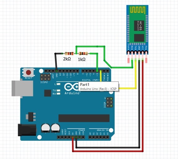
- Connect 5v to 5v
- Connect GND to GND
- Connect Tx to pin 2
- Connect Rx to pin 3 and GND through resistors (2k and 1k) as shown below
- EN and state pins remain hanging
- Remove the 5v connection to HC-05
- Remove the connections to Pin 2 and 3 of arduino
- Connect the arduino to PC to power on using USB
- Upload the sketch below
#include <SoftwareSerial.h>
SoftwareSerial BTserial(2, 3); // RX | TX // Connect the HC-05 TX to Arduino pin 2 RX.
// Connect the HC-05 RX to Arduino pin 3 TX
char c = ' ';
void setup() {
Serial.begin(9600);
Serial.println("Arduino is ready");
Serial.println("Remember to select Both NL & CR in the serial monitor");
// HC-05 default serial speed for AT mode is 38400
BTserial.begin(38400);
}
void loop() {
// Keep reading from HC-05 and send to Arduino Serial Monitor
if (BTserial.available()) {
c = BTserial.read();
Serial.write(c);
}
// Keep reading from Arduino Serial Monitor and send to HC-05
if (Serial.available()) {
c = Serial.read();
BTserial.write(c); }
}
- Keep holding the button on HC-05
- Connect 5v to 5v, the HC-05 will go into AT mode
- Release the button on HC-05
- Reconnect hc-05 to pin 2 and 3
- Execute the following AT commands through serial monitor (make sure the baud rate is set to 9600 and line endings is set to be "Both NL & CR")
AT+ROLE=0
AT+POLAR=1,0
AT+UART=115200,0,0
- Remove the USB connection to arduino
2. Setup hc-05 with PC
- Power arduino with AA cells (4.8 v)
- From the Control Panel select Add a Device.
- Add the Bluetooth module.
- Select enter pairing code option.
- Enter "1234" for the pairing code.
- At the Add a device success window, click Close.
- Device ready to use. The OS will create two serial COM ports associated with the device. Always use the one with the lower number.
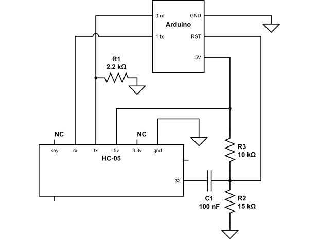
3. Solder a jumper onto Bluetooth module on Pin 32
4. Build ONLY the RESET pin connections and change pin 2 and 3 connections to pin 0 and 1 respectively as shown below - keeping rest all the above circuit the same